Blog 2: Setup
March 1, 2025
Welcome to my second blog! This week, I’ll be discussing the setup that we work with to collect data and some things we did to prepare it. This is what our optical table looks like at San Jose State University and I made a diagram for it.
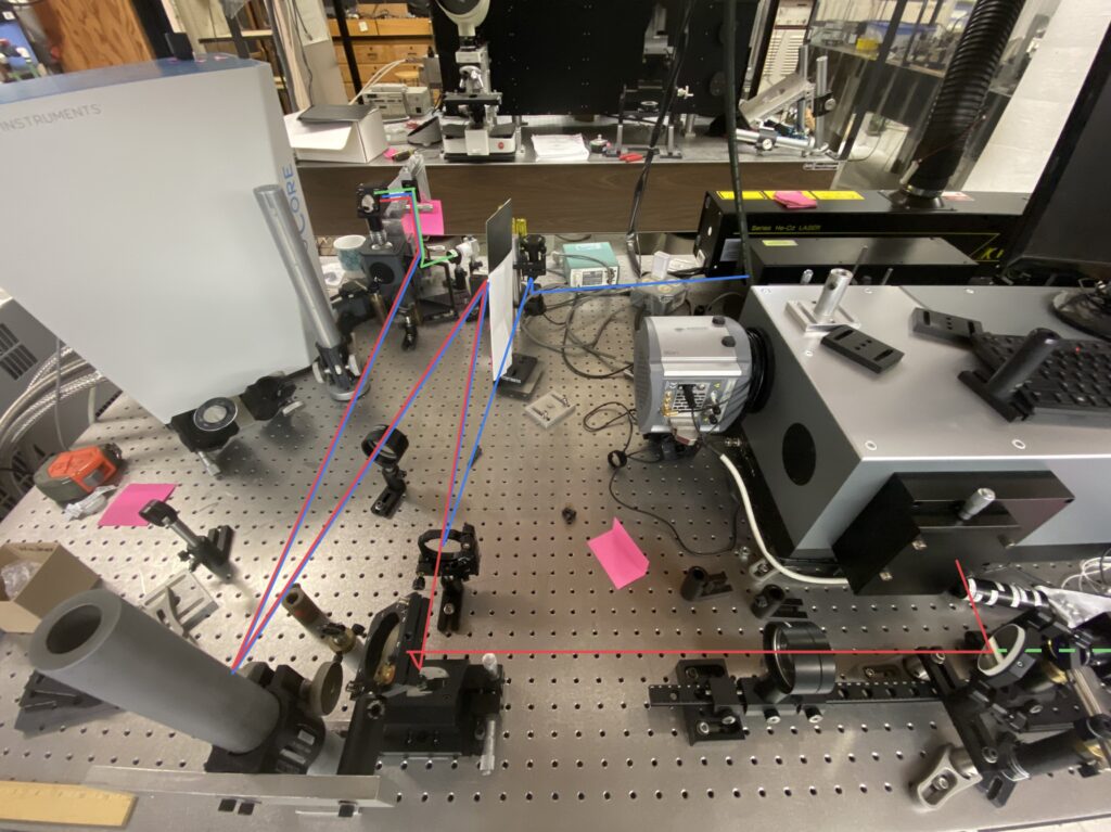
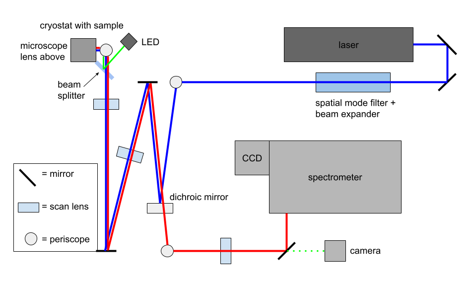
We have a temperature-dependent photoluminescence (PL) spectroscopy and optical microscopy setup. For PL spectroscopy, the laser path is shown in blue, while the emitted light from the sample follows the red path to the spectrometer. For optical microscopy, we remove the mirror at the bottom right and use a white LED. The light travels along the green path to the sample, then reflects and follows the red path to a camera, allowing us to view the sample and ensure proper alignment.
The laser is a He-Cd continuous wave laser with a wavelength of 442 nm. The light passes through a Keplerian spatial mode filter and beam expander, which consist of two lenses with the second one having a longer focal length, and a pinhole in the middle to block side “noise” and produce a clean beam. The periscopes all consist of two mirrors which are at 45° angles to horizontal and change the height and direction of the light beam. Next, the beam hits a dichroic mirror, which reflects shorter wavelengths and allows longer wavelengths to pass through, so the light from the laser reflects. The scan lenses become important after the light reaches the sample and the sample emits light. The microscope objective and first two scan lenses form an infinity optical system, a diagram of which is shown in the picture below. The objective makes the light collimated, and then there is double the focal length between the first and second scan lenses so that we have collimated light going into the third. The third focuses the light into the spectrometer. By collimating the light, we can ensure minimal distortion when other elements are inserted in the beam path.
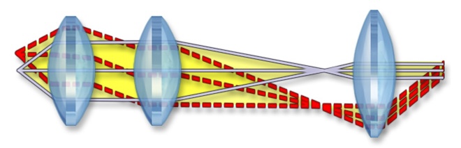
(Infinity Optical Systems. Nikon’s MicroscopyU. https://www.microscopyu.com/microscopy-basics/infinity-optical-systems.)
The spectrometer contains a diffraction grating, which works like a prism, so the light is split by wavelength, and the different pixels of the charge-coupled device (CCD) camera measure the intensity of each wavelength. The beam splitter allows half of the light to go through and half to reflect. In this case, it is there for optical microscopy with the LED.
In order to prepare the setup, one test we did was inserting a helium lamp in the beam path. As elements have known distinct spectral lines, we confirmed the spectrometer was working when we obtained the expected results.
We collected photoluminescence spectra at 3.8 K, 5 K, and, in increments of 5 K, up to 55 K for the gallium arsenide quantum well. Next week, I’ll be finishing up analysis of our first set of data. See you next time!
Reader Interactions
Comments
Leave a Reply
You must be logged in to post a comment.
Impressive you managed to set this up so quickly, I remember taking months to set up my simpler Schlieren imaging system. What’s the difference between a periscope and a mirror in your setup? Why use one over the other?
Actually it was mostly already set up but I am sure it took a long time. There was one time when I was there that we wanted to adjust one piece and we spent 30 min finding an appropriate screw and nut. Periscopes consist of 2 mirrors, one above the other, so it changes the height of the beam path. It is necessary because for example, the light needs to be above the microscope which is higher than the other lenses.
Ah, I see. Thanks and good luck!
Wow, this looks like one of those laser puzzles where you try to angle reflective surfaces for the laser to bounce off of and reorient itself to hit the target. Was all the equipment here provided by the university?
Yes, the lab orders all needed materials.