Blog 8: Applying Theory
May 29, 2026
Hey, sorry for the long delay. While testing, I discovered that the motor I’m using wasn’t powerful enough, so I had to order another one. In the meantime, let’s discuss how I came to that conclusion.
Following what I’ve finished in Blog 6, I’ve begun testing the different electronic parts to see if they work.
The most important of them all is an STM32 microcontroller, the brain of the build. While I got it almost a month back, I didn’t really want to work on it until I had the hardware almost complete.
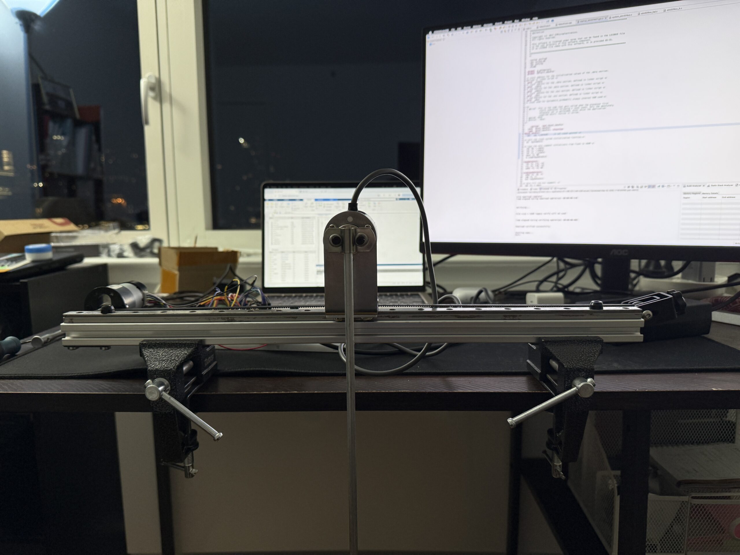
Speaking of hardware, it took me a while to gather all the pieces to even build something that resembled a pendulum, let alone something that works to balance itself. While on the surface, it may seem easy, just buy a rail and cart, something to bolt them to, a motor, something to connect the motor to the cart, the encoder, and the pendulum itself. In reality, most of these did not want to work with each other from the get-go. I had to look out for specific parts that helped them do so, and this was the part that took me a while to get right.
But anyway, back to electronics. The STM board had a built-in LED and button, so I wrote a program that turns the LED on and off with the press of the button to confirm that the board itself works. Then I tried both the rotary encoder for the pendulum angle and the encoder for the motor’s position at the back of the motor, and luckily, both worked. Then, the last step is to test whether the motor spins and whether the motor driver controls its speed.
Because the power supply provides a constant 12V, the motor needs a regulator to adjust that voltage so it spins at different speeds. The driver does so by using a technique called Pulse Width Modulation (PWM). Basically, it outputs square waves that, after filtering, the motor sees as a constant voltage fraction of 12V.
After I’ve tested and confirmed that all the components work, I finally put them together into a pendulum.
Then comes the hardest part of this project, the Sim-to-Real gap.
Initially, I tried using the exact numbers that I calculated in MATLAB as the K for LQI, but the results were underwhelming.
After more testing, I was able to get it to almost work.
But see that shake? That is where I began suspecting the motor was the problem. Those oscillations seem to come from the fact that the controller can’t pull the cart back quickly enough after an overshoot. This is a torque problem. Initially, I chose a motor with a low gear ratio for a faster maximum speed, but it seems like, for a project like this, higher torque is necessary.
And this brings us to where I am right now, waiting for the new motor to arrive. Tune in next time to see if the new motor makes any difference!
Leave a Reply
You must be logged in to post a comment.