
Week #12: Flight
May 15, 2026
Intro:
Welcome to Week 12 of my blog. This was the final week, and I’m proud to say that I made the most of it. I feel like I’ve completed weeks worth of work since last Saturday, but it was all worth it in the end. Let’s get into it:
Transmitter and Receiver Work:
Original Transmitter and Receiver:
Last week, I tried setting up my RP3 Receiver and Radiomaster Pocket Transmitter. I thought that, given the ELRS communications protocol, I would have to wire it to the SBUS OUT port on my Pixhawk 6C:
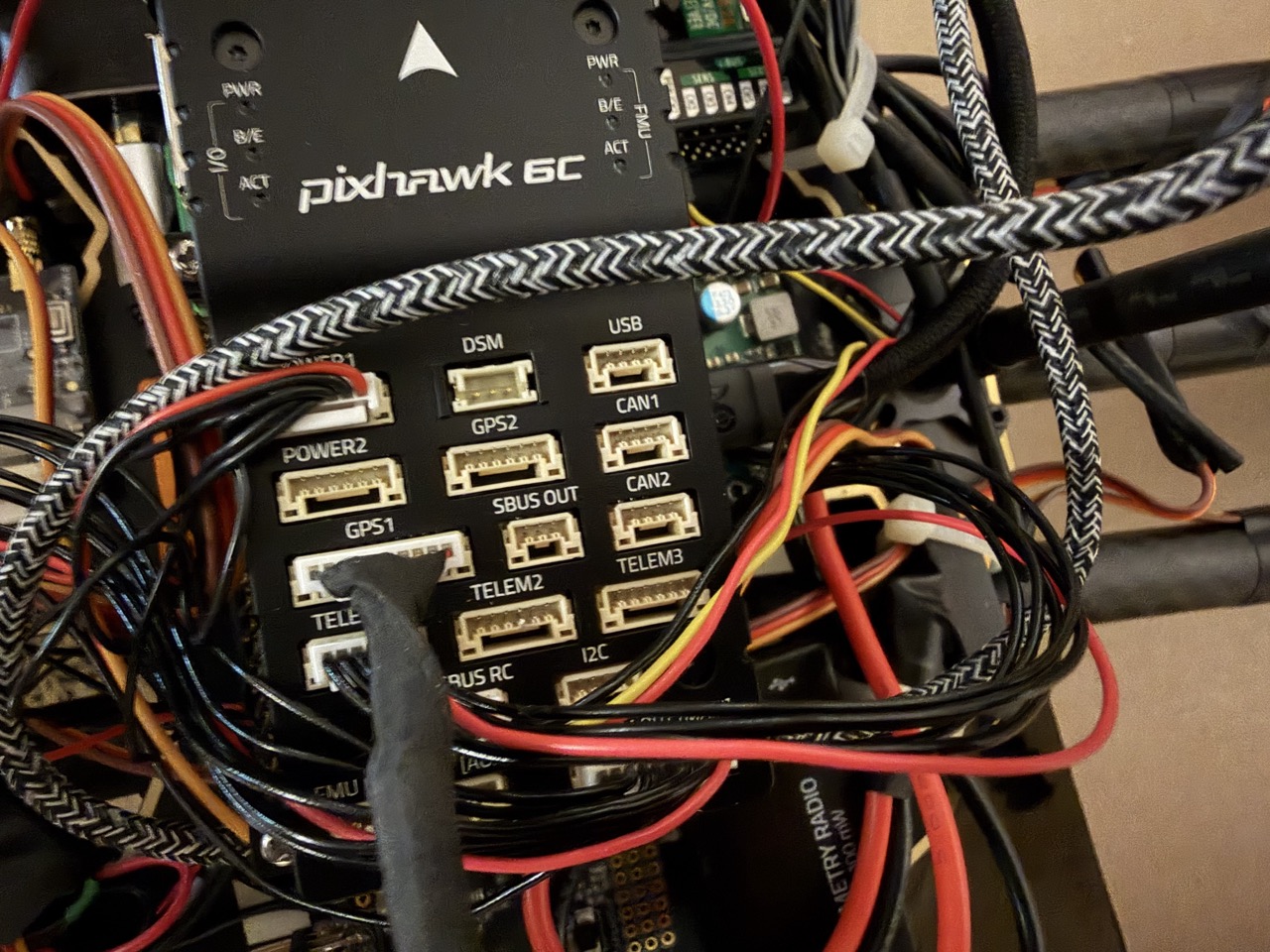
Figure 1. SBUS OUT port on Pixhawk 6C. Photograph by author, 2026.
To do this, I cut off the end of one 3-pin JST-GH cable, stripped and tinned it, and then soldered it to the -, 5V, and T sockets on the RP3:
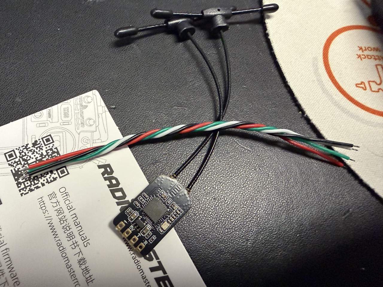
Figure 2. RP3 Receiver sockets. Photograph by author, 2026.
With this, the RP3 could at least be powered on and connected to the Pocketmaster controller.
However this week, when I tried to connect it to my laptop via Mission Planner, it couldn’t locate the RP3. I then realized the SBUS OUT was an output port, and not an input one. So, I swapped it to the PPM/SBUS RC port, requiring me to redo the entire wire-prep process with a 4-pin JST-GH wire instead, and add a wire going to the R pad:
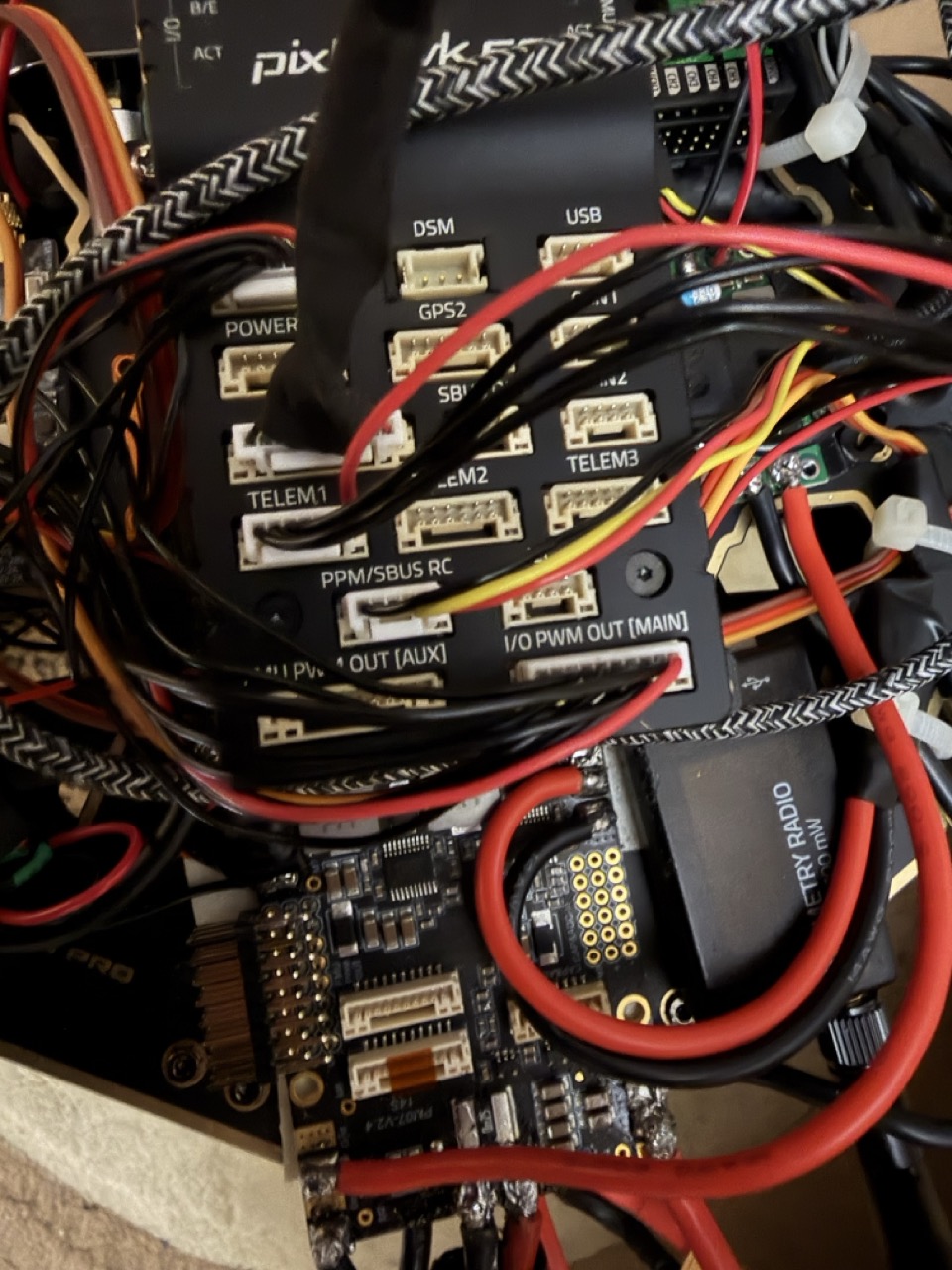
Figure 3. PPM/SBUS RC port on Pixhawk 6C. Photograph by author, 2026.
However, this didn’t work either. After reading up online, I realized that since the RP3 outputs CRSF protocol it’s T-pad, I would need to use a port that had a UART protocol to read it, which would be a telemetry port. So, I redid the entire wiring process with the TELEM2 port (refer to Figure 3 above). The final result looked like this:
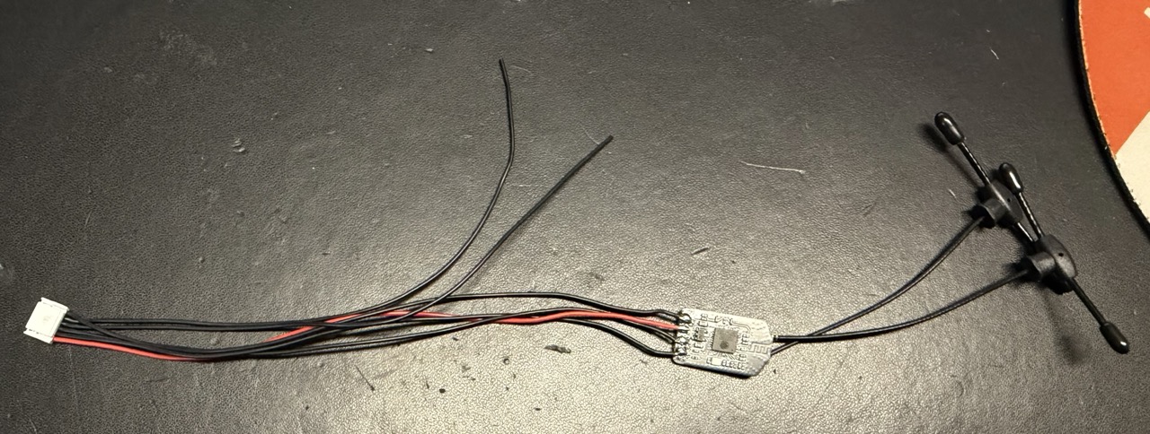
Figure 4. RP3 soldered to 6-pin JST-GH cable. Photograph by author, 2026.
However, this didn’t work either! At this point, I was rather done with the RP3 and Radiomaster. The Radiomaster Pocket itself was an extremely high quality and powerful transmitter, but I had no clue how to set it up. Online setup tutorials were lacking as well.
Final Transmitter and Receiver:
So in the interest of time, I decided to replace this setup with a FlySky FS-i6X transmitter and FlySky FS-iA6B receiver. I flew my previous drone with them, and I was familiar with the setup and calibration processes.
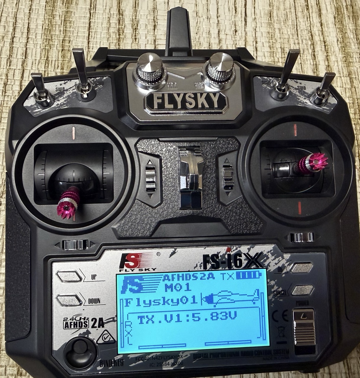
Figure 5. FlySky FS-i6X Transmitter. Photograph by author, 2026.
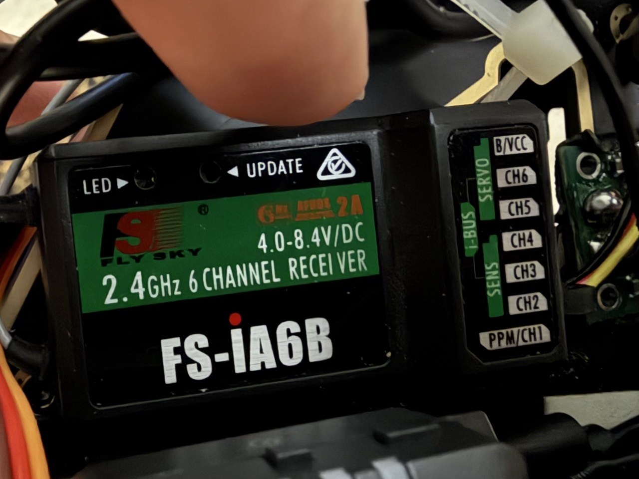
Figure 6. FlySky FS-iA6B Receiver. Photograph by author, 2026.
ESC Wiring:
With the transmitter and receiver work out of the way, I moved onto wiring in the ESCs to test the motors. On my old drone build, the pins that connect to the ESCs were a part of the flight controller (Pixhawk 2.4.8):
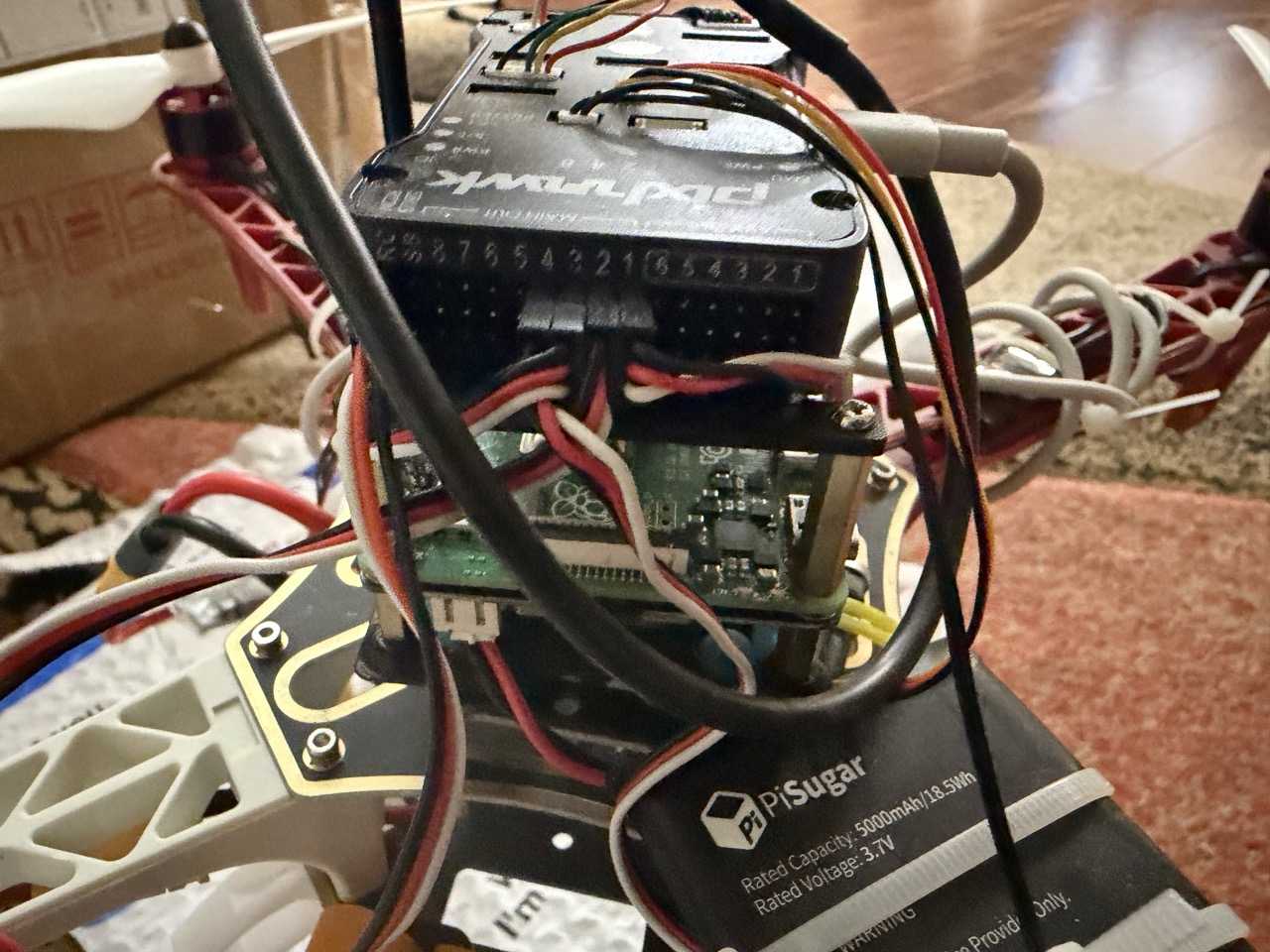
Figure 7. Pixhawk 2.4.8 ESC wiring. Photograph by author, 2026.
But the Pixhawk 6C was a different story. Instead of having these pins built in, the Pixhawk 6C has a PWM EXT board (external board), that I had to find space on the top plate to mount:
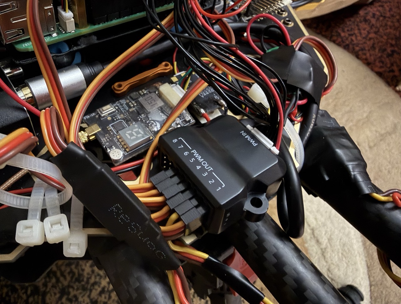 Figure Figure 8. Pixhawk 6C ESC wiring with PWM EXT board and ESC wire extenders. Photograph by author, 2026.
Because the board was on the left side of the drone, I needed ESC wire extenders to make the ESC wires reach. Since the connection was very loose. I put heat shrink on the connector, connected the two wires, and used a heat gun to cover the connection with the heat sink, providing it with stability (refer to black cover in Figure 8 with text “ReSuoG”).
Maiden Flight:
With the ESCs wired, motors tested, and transmitter calibrated, it was time for my drone’s maiden flight. As I set everything up at the park, I was quite nervous if the drone would even take off at all. It was designed for a lighter weight and smaller ESCs. There was a world where it couldn’t get itself off the ground.
But I was confident in my math and parts selection. Given the time I spent research, building, and testing, everything should work. And I’m proud to say that it did. My drone had a smooth liftoff, and didnt struggle to carry its weight. This was huge. However, what happened next was less than ideal. For some odd reason, the drone started drifting to the right, without any translational input from my transmitter. Luckily I was able to ground it (with a bit of a crash landing). I tested this a few more times, and figured out that one of my propellors had been installed upside down. I fixed this and flew again, but to no avail. At this point, I had gathered enough data for now, and headed home
It turned out that two of the propellers had been chipped after the first crash. Thankfully, I had ordered spares 10 weeks ago, and was able to swap them out with ease. After examining the logs, it appeared that I needed to recalibrate my accel, to fix the rightward drift. I did this and headed out the next day
Attempt 2:
On my second day of flights, I saw some greater success. This time, the drone didn’t just drift to the right! It instead drifted backwards, and a bit to the right. This meant that my fixes the day before had helped, but there was still something going on here. I was going to conduct a few more tests, but as I was lifting the crashed drone and preparing for another flight, one of the arms came loose. I think this is an aftereffect of the less than graceful landings. However, it “encouraged” me to look over my drone again, and ensure that every screw has been tightened.
There was another issue as well. My PM07 power module had a built in capacitor, that helped regulate the voltage the electronics (GPS, Pixhawk, etc.) received. Without it, the extra voltage may have interfered with the electronics’ readings, compromising the flight. The capacitor comes pre-soldered to the PM07, but the connection was extremely thin and fragile, and in this last flight’s crash landing, it broke. So, I had to fix it.
I intially struggled to do this, as the capacitor’s legs were quite short, and quite far from the PM07’s pads. I started by adding large amounts of solder to form pillars that I could attach the legs to. However, because the positive and negative pads were quite close, they often combined:
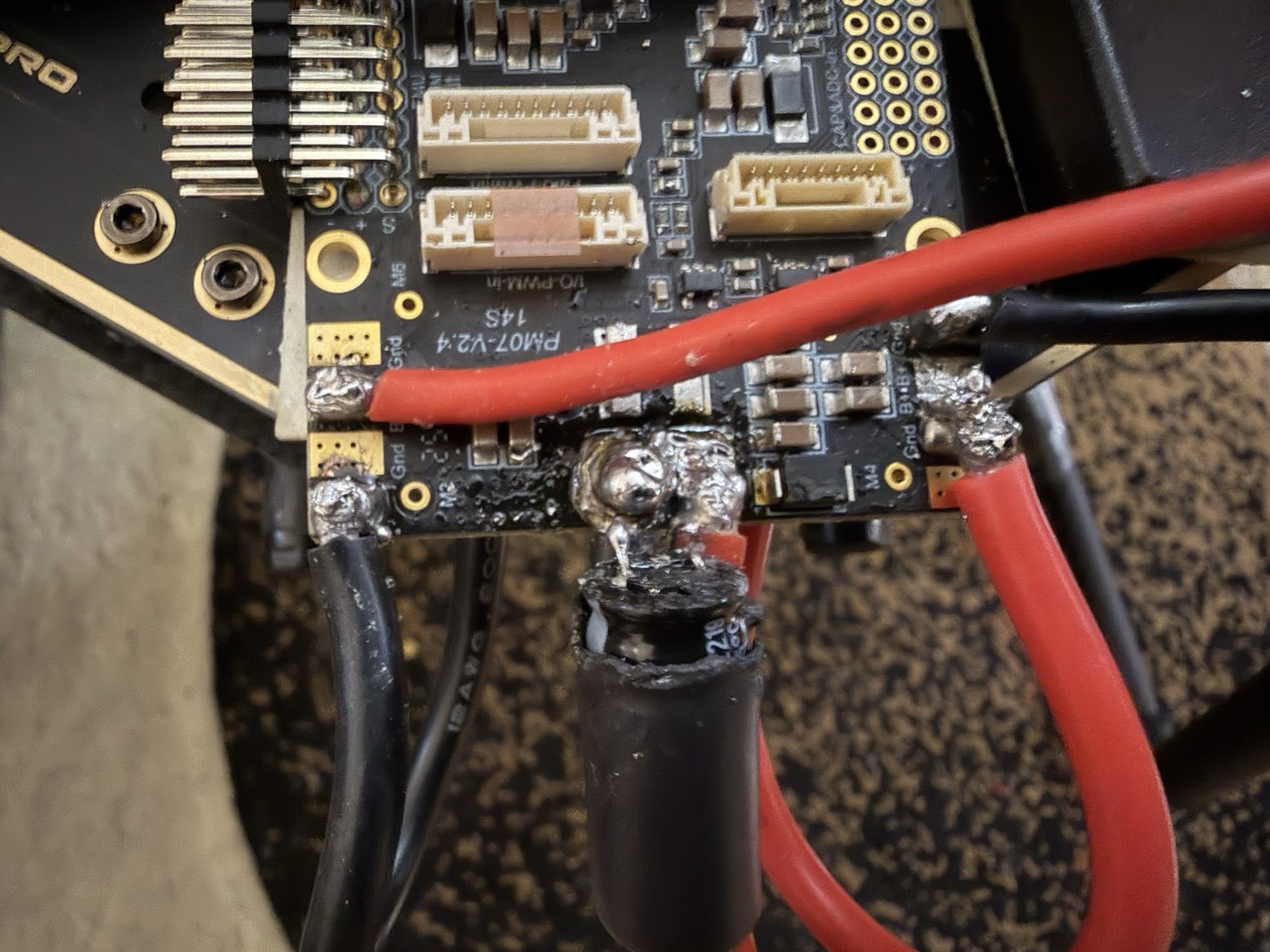
Figure 9. Combined positive and negative terminals. Photograph by author, 2026.
If I had plugged in the battery then, I would have shorted the entire board. I didn’t do that of course. But I wouldn’t be able to fly if it remained like this.
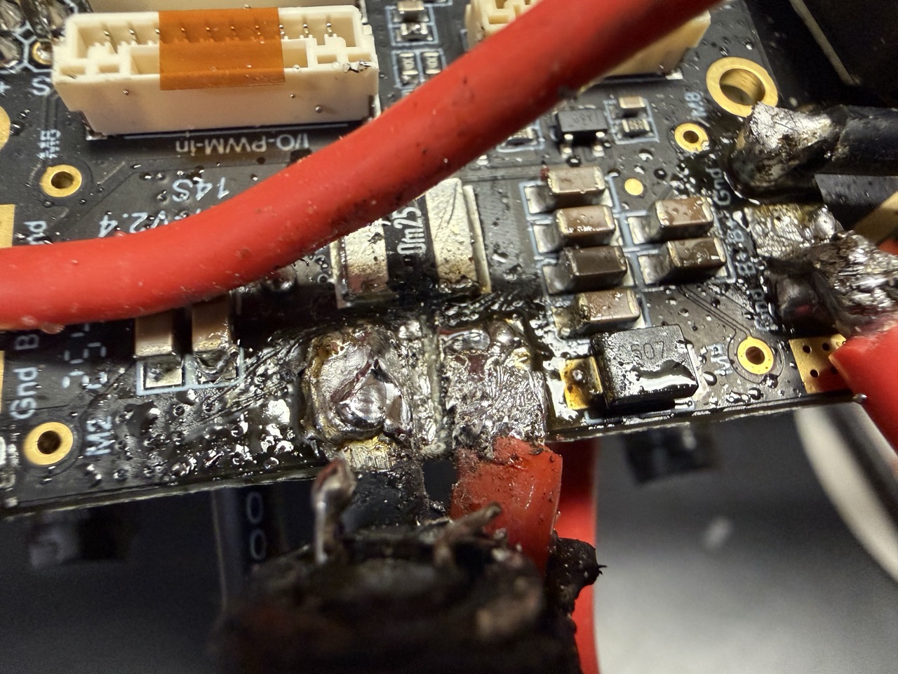
Figure 10. Separated positive and negative terminals. Photograph by author, 2026.
I separated the terminals with my soldering iron, and went for a different approach. I instead soldered 14AWG wires (20 or 22 would have been better but 14 is smallest I have), to the capacitor legs on one end, and to some free + and – terminals to the other end (and removed it from its covering to mount it in a safer place):
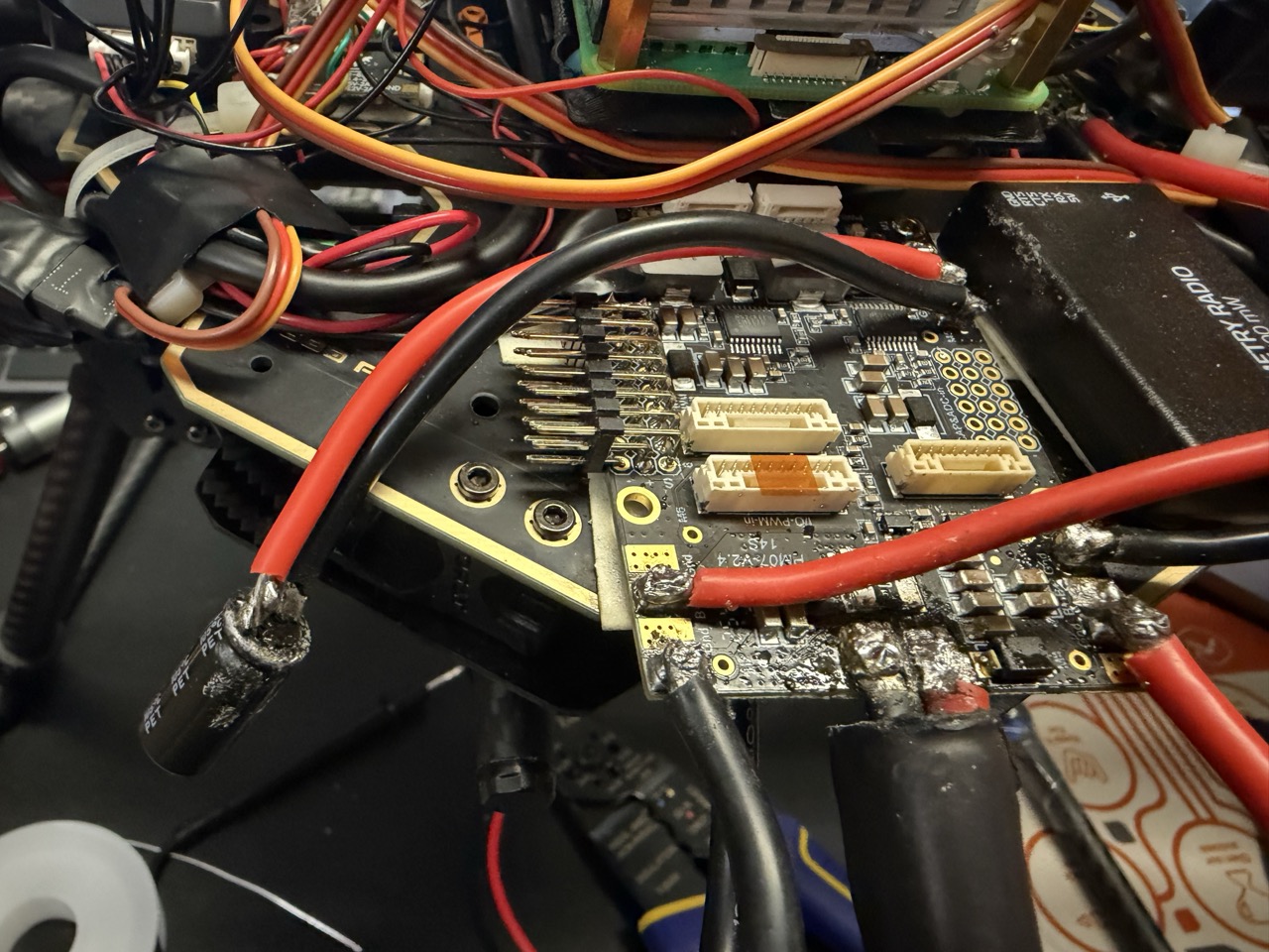
Figure 11. Reconnected Capacitor. Photograph by author, 2026.
Attempt 3:
During my first two attempts, I had been flying the drone in Stablize mode, which gave me direct control over the vertical acceleration with my sticks. However, after rewatching the flight tutorials I used in my science fair drone build, I realized that flying in Loiter mode might do the trick. Here’s the result:
Figure 12. Successful Flight. Video by author, 2026.
As you can see, the drone flies! I am extremely happy that it worked, because it means that all of my research into the appropriate electronics, motors, ESCs, etc., was correct. It certifies that I know how to design a custom drone stack given specific mission parameters.
I was also able to record the RunCam and thermal camera streams during this flight:
Figure 13. RunCam Recording. Video by author, 2026.
Figure 14. Thermal Camera Recording. Video by author, 2026.
Conclusion:
I don’t have any questions for my readers this week. The technical work is done. All that’s left is to present it. Stay tuned for that, and see you next time!
Reader Interactions
Comments
Leave a Reply
You must be logged in to post a comment.
Hi Anav. Really impressive persistence through all the wiring, and flight testing, especially working through each issue and completing the drone’s flight. Great end to the project!