Stuck in diaphragm hell (Shock Tube Blog #10)
May 3, 2025
Hi all!
Sorry for the lack of comms last week, I didn’t feel like I’d made enough progress to really show off. As it turns out, designing a diaphragm with appropriate thermal and electrical conductivity that’s safe for vacuum is quite difficult. The goal of the diaphragm is to hold the pressure from the driver tube until the time comes to trigger the testing run, at which point electrical current is passed through a heating element in the diaphragm, causing it to break and allowing the air to burst through the driven tube. It would probably be fine if I’d allowed myself to use hot glue, tape, solder, etc., but I wanted to be safe; it was still possible that even under the very rough vacuum I was pulling, these could outgas some potentially dangerous substances. Therefore, along with the PLA plastic, I could only really use materials like copper, stainless steel, aluminum, and J-B weld. I was even more limited by the fact that my aluminum wire was difficult to connect through electrical contact(potentially due to some thin non-aluminum coating?) and that J-B weld is difficult to consistently work with on a small scale and is likely an electrical insulator. After several iterations, I think I came up with a relatively easy and fast process to manufacture diaphragms with consistent properties. This is quite long and honestly as much for myself as for this blog, so feel free to skip over it if you aren’t interested.
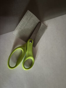
1. I cut out a small piece of stainless steel mesh. This is easy to do with just normal scissors, but the mesh fibers are extremely thin and carelessness can lead to cuts. Although stainless steel is a good electrical conductor, the low thickness gives it a slight resistance of about 0.9 ohms, which provides adequate power when connected to the 12V 12.5A power supply(I believe the wiring to and from the testing room will provide >0.1 ohms of additional resistance).
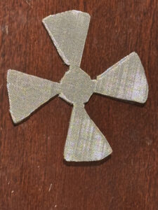
2. I printed out two cutting stencils without bed glue. After aligning them and clamping them down against the mesh, I got out my exacto knife and cut along all the stencil lines. I then put away the stencils and cut out the final pieces of connecting mesh. Lastly, I bent the fins upwards slightly to ensure that holding the fins down also held the central bit against the diaphragm plate. These stencils were really useful in allowing me to consistently cut diaphragm heating elements in the same shape, which is instrumental when trying to predict what pressure the diaphragm will fail at given a certain heating time.

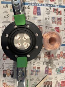
3. With the heating element done, I printed out two more cutting stencils and grabbed a 3 inch silicone O-ring. I then clamped it in, poked four holes in it using a sharp screwdriver, and inserted four 12+ inch 1.3 mm pure copper wires. These wires serve a dual purpose. Anchored to the outside of the tunnel, they kept the four major fragments of the diaphragm from being flung through the tunnel by the shockwave. They also serve as electrical connections to the heating element. It is true that these wires might introduce leaks through deformation of the O-ring, but since the O-ring would be on the side of the system with atmospheric pressure until after the diaphragm is triggered, these leaks are likely inconsequential.
4. I then printed out the diaphragm plate, removed all the 3D support, and placed the O-ring into the slot. For each wire, I pulled it out until it met the other side of the O-ring, and then wrapped it around the 3D supports. I had initially planned to use J-B weld for this, but as I mentioned before, it was hard to work with on this small scale, and a small slip-up could leave the copper wire covered in a thin layer of it, making the electrical connection extremely difficult and inconsistent. It also required PPE and at least a day to dry, and after testing, the connection wasn’t very strong. Using supports like this made things way easier, and the only real downside would be that I’d have to be more careful about the copper touching the inner part of the diaphragm.
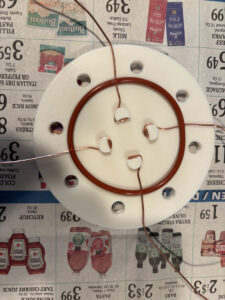
5. I then got the heating element from earlier, carefully positioned it in the middle, and used some thin copper wire pieces to electrically connect the ends of the diaphragm to the copper wire. One of these was also a mechanical connection, to ensure that the heating element also doesn’t get flung across the tunnel. I didn’t need to solder anything, since I made the second diaphragm plate compress both electrical connections.

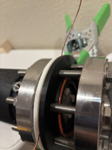
6. Finally, I printed the other diaphragm piece and aligned it such that the grooves fit into the thick copper wire. This is a bit finicky, but since copper is so flexible, it’s usually not a problem. The final assembly can be clamped until ready to bolt in.
7. Final installation just consists of unbolting, taking out the previous diaphragm, adding the other two O-rings, and rebolting the new diaphragm in. I also wrapped the copper wire around the connection anchor on the driven tube, and connected them to the positive and negative wires from the control room. As a quick point of safety, the flange is also wrapped in electrical tape to ensure none of the bare metal wires make contact with it, and I made sure my power supply had short-circuit protection.
 In hindsight, I probably should have at least tested the diaphragm, but I don’t have many doubts that it will at least heat up. This represents the last major component I still had to design and build! I’m currently making finishing touches and should be ready to finally do a full test of the system on around Tuesday(fingers crossed). Thanks for reading and see you later, hopefully with the results!
Leave a Reply
You must be logged in to post a comment.